
In feed mills, the cyclone dust collector (commonly referred to in the industry as a “cyclone”) utilizes centrifugal force to separate feed dust from high-temperature, high-humidity airflow. This process requires no filter media—unlike pulse-jet dust collectors, which rely on filter bags—and functions entirely through mechanical dynamics. The process can be broken down into the following four key steps:
1. Tangential Air Intake and Formation of an Outer Vortex
Dust-laden hot air from the cooler enters the cyclone through a tangential inlet located on the upper side of the unit at a velocity of approximately 20 m/s. Guided by the circular structure of the cyclone’s outer casing, the airflow transitions from linear to circular motion. Driven by the negative pressure generated by a fan, the air forms a high-speed, downward-spiraling vortex (the “outer vortex”). Additionally, an exhaust pipe extends from the top into the interior of the unit, preventing air from short-circuiting directly to the fan and ensuring effective separation.
2. Centrifugal Separation and Impingement against the Casing Walls
As the air rotates at high speed, feed dust particles—which have a higher density than the air—are subjected to intense centrifugal force (typically around 2,000 times the force of gravity). This force “flings” the dust particles toward the inner walls of the cyclone, where they collide with and rub against the surface, losing their rotational kinetic energy.
3. Gravitational Settling into the Bottom Hopper
Having lost their kinetic energy, the feed dust particles descend in a spiral pattern along the inner walls of the cylindrical and conical sections. They eventually settle into the hopper located above a rotary valve (airlock) at the base. The rotary valve then discharges the collected dust, which is typically conveyed to a finished-product elevator, allowing for the recovery of the material.
4. Airflow Reversal and Discharge of Purified Gas
When the swirling gas reaches the lower end of the conical section, the narrowing shape of the cone forces the airflow toward the center. The air is compelled to reverse direction, moving upward along the central axis while maintaining its original rotational direction—a phenomenon known as an “inner vortex” (or inner cyclone). By this stage, the majority of the dust has been separated; the purified air then exits through an exhaust pipe inserted into the center of the top cover and enters the downstream ductwork system.
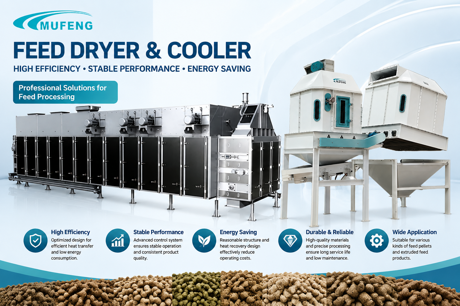
Why, then, does dust frequently escape?
1. Clogging of the rotary valve (airlock), preventing dust discharge.
The gas entering the cyclone separator after the cooling process is typically high-temperature and high-humidity. Upon contact with the walls of the cyclone or the downstream ductwork, this gas condenses into water droplets. These droplets run down the inner walls and accumulate at the top of the rotary valve—a problem particularly pronounced during winter. This is precisely why the cyclone separator and its subsequent ductwork require thermal insulation. When this liquid reaches the top of the rotary valve, it mixes with the feed dust, causing the dust to clump or adhere to surfaces. If left uncleaned, these accumulations can block the discharge passage. Consequently, the dust separated by the cyclone cannot be discharged; instead, it is caught by the high-speed, negative-pressure airflow generated by the fan and carried into the exhaust duct, ultimately being expelled from the system.
2. Damage to the internal exhaust pipe (the section extending into the cyclone), creating a “short-circuit” in the airflow.
In a cyclone separator, the exhaust pipe extends a certain distance into the unit’s interior; this design is essential for inducing the rotational flow required to separate feed dust from the air. If the wall of this internal exhaust pipe develops cracks or holes, the high-speed, tangentially entering airflow may pass directly through these openings into the exhaust duct—bypassing the intended cyclonic separation process entirely. In this scenario, feed dust fails to fully separate from the airflow and is instead discharged, resulting in a “dust leakage” phenomenon. This is particularly noticeable during the winter, often accompanied by white, high-temperature, high-humidity steam.
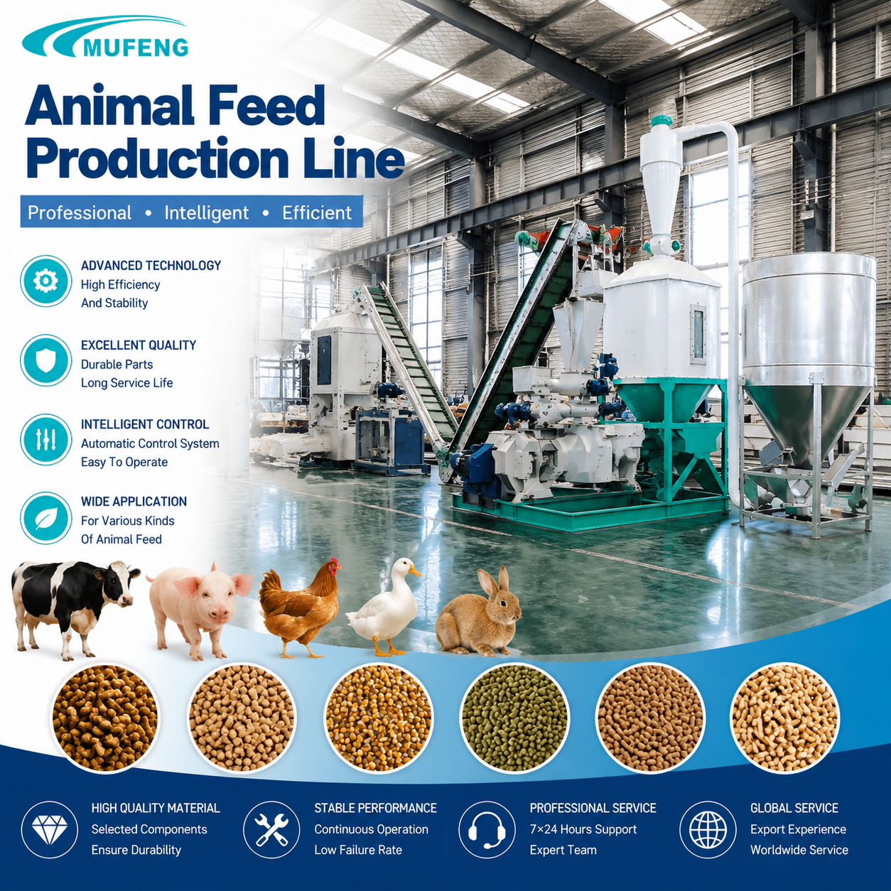
3. The fan airflow volume is set either too high or too low.
If the airflow volume is too high, the negative pressure differential becomes excessive, causing the feed dust—already separated by the cyclone—to be drawn back into the airstream. Conversely, if the airflow volume is too low, the centrifugal effect within the cyclone is insufficient, which may also allow dust to escape.
4. Issues with the airtightness of the rotary valve (airlock).
If the rotary valve lacks proper airtightness, airflow from the elevator system may be drawn in. This effectively reduces the airflow on the cyclone dust collector/cooler side, weakening the cyclone separation efficiency and causing settled dust to be re-entrained and carried away.
5. Damage or leaks in the cyclone body wall, disrupting the rotating airflow.
A breach in the cyclone body wall compromises the integrity of the entire system—specifically the path from the high-temperature, high-humidity steam inlet (at the cooler) through the tangential entry and the cyclone chamber, and into the exhaust duct. This weakens the cyclone effect, leading to incomplete dust separation.
In summary, when a cyclone dust collector experiences abnormal dust leakage, one must systematically investigate several potential causes: whether the rotary valve is discharging dust correctly, whether the internal ductwork within the cyclone is damaged, whether the airflow volume is set appropriately, whether the rotary valve’s airtightness is compromised, or whether the cyclone body wall itself is damaged. A thorough inspection will invariably reveal the root cause.