
1 Purpose
To establish an SOP for feed retention chambers, ensuring standardized operation.
2 Scope of Application
Applicable to the control and operation of feed retention chambers in all feed mills.
3 Responsible Person
Pelleting Operator.
4 Management Content
4.1 Pre-Startup Preparation
In addition to completing pelleting machine pre-startup tasks, the pelleting operator shall prepare for the retention chamber as follows:
Check the jacketed steam inlet pressure (for jacketed systems, strictly ensure pressure does not exceed 0.1 MPa), sensitivity of the safety valve, and status of the steam trap bypass valve (confirm if it is open); for electric heating jacket systems, verify that the temperature is controlled within 70–80°C.
Check if the retention chamber door cover is tightly fastened and the seal is intact.
Adjust the retention chamber’s operating frequency according to the required product type.
4.2 Startup and Shutdown
4.2.1 Startup Sequence
First, activate the pelleting auxiliary system in strict order: Centrifugal Fan → Pellet Cooler → Air Lock Valve → Pelleting Machine Bypass. Then, start the Lower Conditioner → Retention Chamber → Upper Conditioner → Feeder.
4.2.2 Shutdown Sequence
Reverse the startup order: Feeder → Upper Conditioner → Retention Chamber → Lower Conditioner → Pelleting Machine → Air Lock Valve → Pellet Cooler → Centrifugal Fan.
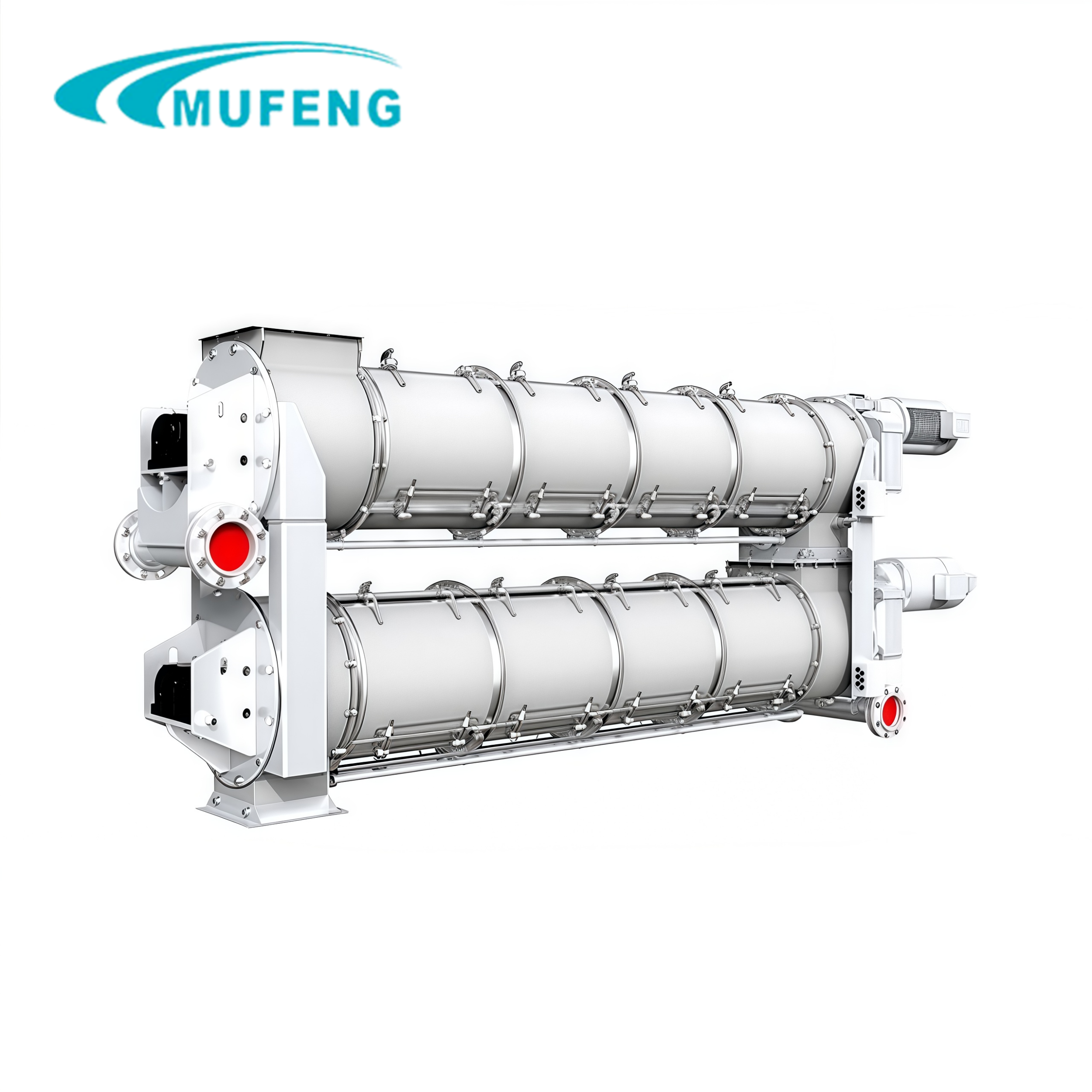
4.3 Operation Precautions
Steam addition method: Only the upper conditioner is supplied with steam (either multi-point or single-point acceptable); no steam is introduced into the cavities of the retention chamber or lower conditioner.
Both inlet and outlet of the retention chamber are equipped with temperature sensors. The operator shall adjust steam based on the retention chamber inlet (upper conditioner outlet) temperature (this must also serve as the access point for the automatic control system). During pelleting, refer to the retention chamber outlet (lower conditioner) temperature. A temperature difference of 1–3°C between inlet and outlet during normal production is a normal phenomenon.
Both inlet and outlet conditioning temperatures must strictly comply with the pelleting process parameter requirements specified in the product formula.
4.4 Daily Maintenance and Precautions
Lubrication management: Replace reducer lubricating oil (L-CKC220 industrial gear oil) after the new equipment runs for 500 hours; replace it every 6 months thereafter (the reduction gearbox must be thoroughly cleaned before refilling). Both end bearings must be cleaned with kerosene every 1000 hours of operation, inspected for wear, and re-lubricated with domestic Grade 2 extreme-pressure lithium-based industrial grease.
Routine inspection: Check the operation status of the reducer, motor, and bearings at least once per week.
Shutdown procedure: After production is complete, run the equipment empty for 2–5 minutes to discharge all internal materials before shutting down.
Abnormal handling: If the retention chamber vibrates violently during operation, immediately stop the machine for inspection, identify and eliminate the fault before restarting.
Blockage/power failure handling: If the retention chamber is blocked or unexpected events such as power failure occur, completely empty all residual materials before restarting. Feed only after the rotor rotates smoothly; no-load startup is strictly prohibited.
Safety during maintenance: To prevent accidental motor startup during maintenance/repair, cut off and lock the main power switch, and place “DO NOT OPERATE” warning signs in front of the central control room electric cabinet and the retention chamber’s local controller respectively.
Door cover maintenance: Inspect and clean the maintenance door cover at least once per week to ensure tight fastening and intact sealing.
4.5 Cleaning
4.5.1 Jacketed System Cleaning
Use boiler exhaust steam for drying. Before production in the next shift, start the retention chamber and both conditioners; after all materials are discharged, open the door cover to check if the auger blades are cleaned. If the jacket is not used, strictly follow the cleaning requirements for conditioners in the Equipment Cleaning Frequency Schedule.
4.5.2 Electric Heating Jacket System Cleaning
Before startup, start the retention chamber and both conditioners; after all materials are discharged, open the door cover to check if the auger blades are cleaned. Turn on the electric heating jacket 20 minutes before production and keep it powered on for 20–30 minutes after production ends to dry with residual heat.
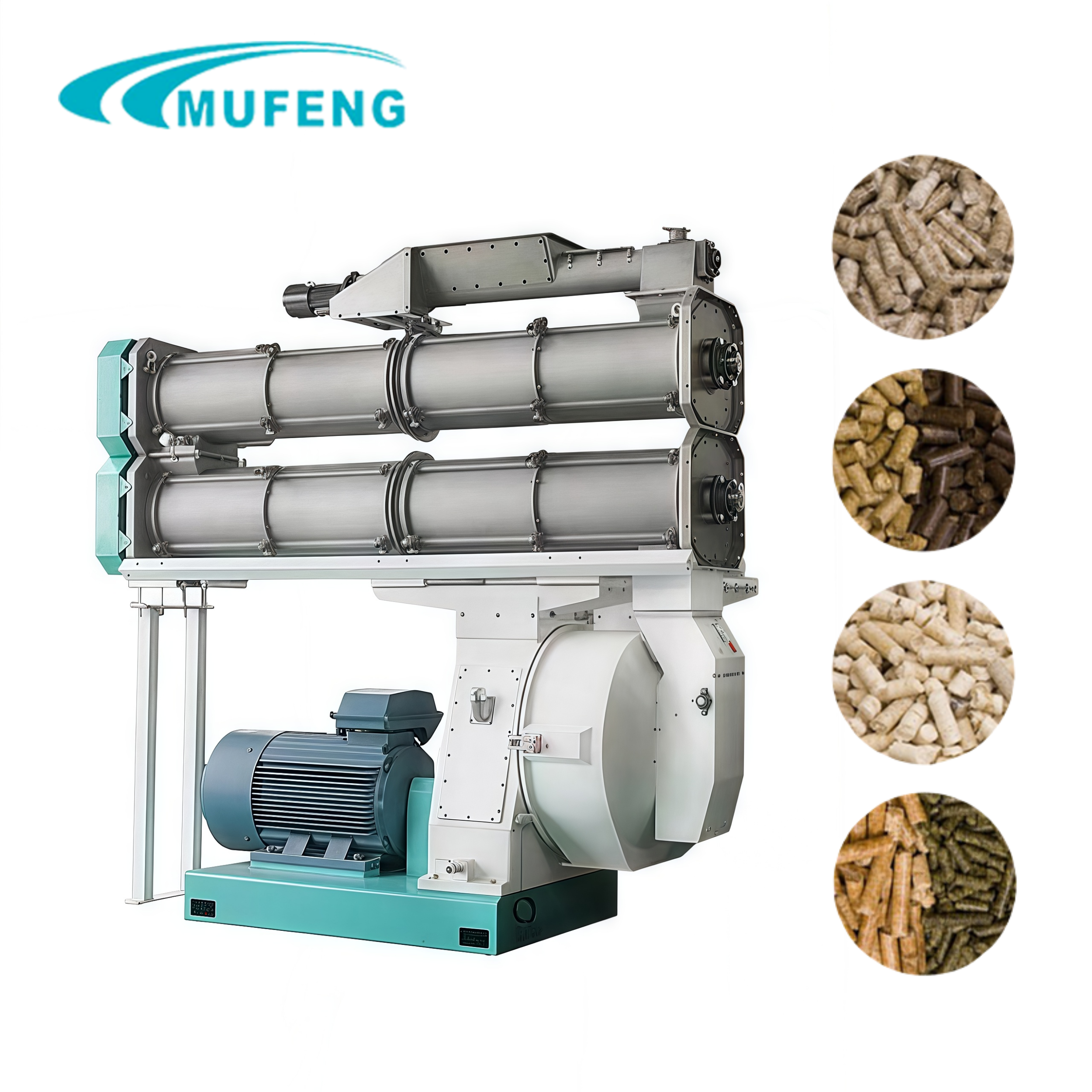
4.6 Attachment: Configuration, Installation, and Commissioning Precautions for Retention Chamber
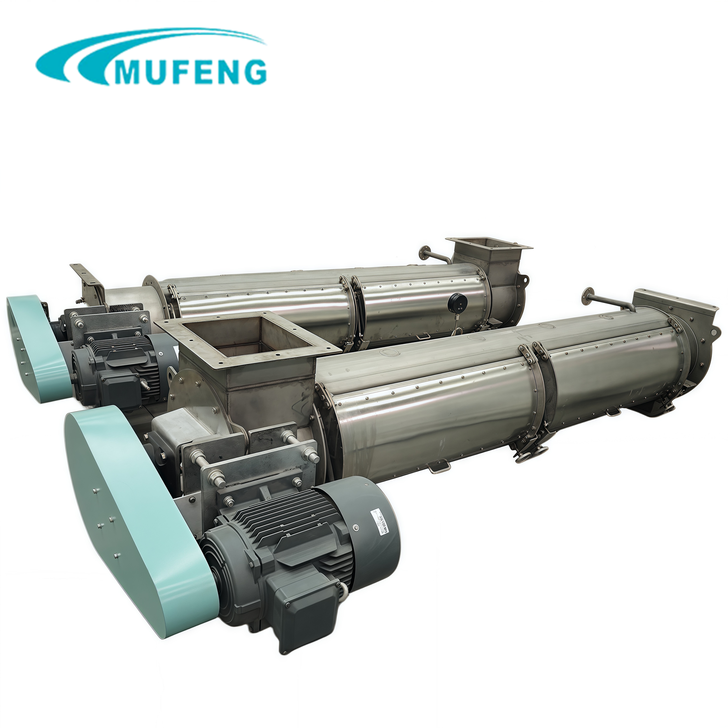
Configuration principle: Select a retention chamber matching the company’s production process requirements. Arrange the steam addition, conditioning, homogenization, and discharge systems reasonably; ensure smooth material conveying between the upper conditioner, retention chamber, and lower conditioner/scattering mechanism.
Core components: Feeder, upper conditioner, retention chamber, lower conditioner (or scattering mechanism).
Temperature monitoring: Both inlet and outlet of the retention chamber must be equipped with temperature sensors. The operator shall adjust steam based on the retention chamber inlet (upper conditioner outlet) temperature (this must also serve as the access point for the automatic control system). During pelleting, refer to the retention chamber outlet (lower conditioner) temperature.
Steam pipeline installation: Comply with local laws and regulations for industrial steam pipeline installation. The pipeline shall have an upward inclination of 1°; add a drainage point at each low point of the main and branch pipelines, spaced every 30–50 meters at their ends.
Pressure control: Follow the principle of “high-pressure transmission, low-pressure use”. The pressure reducing valve shall be installed 5–10 meters away from the upper conditioner’s steam inlet with no more than 5 elbows in between. The pipe diameter after pressure reduction shall be increased (e.g., DN40 to DN50) to ensure stable steam flow.
Insulation requirements: Use an electric heating jacket or steam jacket for insulation. If using a steam jacket, strictly ensure the inlet pressure does not exceed 0.1 MPa; the supporting safety valve, steam trap, and bypass stop valve must be guaranteed to operate safely and effectively. If using an electric heating jacket, it must be controlled by a dedicated controller and temperature monitor.
Operating frequency optimization: For the optimal retention time required for different materials, the company shall organize relevant personnel to test moisture content before and after conditioning according to the formula, analyze data on moisture changes and operating frequency, determine the optimal operating frequency for each product, and post the frequency schedule on-site near the equipment. Prepare for ring die optimization based on conditioning moisture, conditioning temperature, and product quality.