Extrusion Processing Technical Process: Common Operational Problems of Single-Screw Extruders During Operation

DATE : Apr 15th, 2026
Read :129

Causes of Material Backflow to Extruder Feed Inlet

Several factors may cause material to backflow into the extruder feed inlet, all of which ultimately stem from a reduction in the extruder’s conveying capacity. The specific factors are as follows:a) Feed rate exceeds the maximum throughput capacity of the extruder screwIf the feed rate exceeds the screw’s handling capacity, material will eventually backflow to the extruder feed inlet. For single-screw extruders, theoretically, increasing the screw speed can enhance this throughput. However, the extruder’s transmission components, such as the gearbox, limit a significant increase in screw speed. Before drastically changing the screw speed, the adjustable range should always be verified.b) Excessive steam injectionWhen the steam injection rate is 1-4% of the dry material handling rate, it has no impact on the screw’s conveying capacity. If the injection rate exceeds this range, the injected steam may block material passage through the steam injection zone, leading to backflow to the feed inlet. Reducing the steam injection volume resolves this issue.c) Excessive resistance during extrusion processingHigh resistance is often caused by structural resistance of the screw before the die head or excessively small die plate perforation area. A sudden increase in resistance can be observed through the pressure reading before the die head, which causes over-filling of the extruder barrel and thus backflow. Increasing the die plate opening area solves this problem.d) Wear of screw elements and barrel linerWorn screw elements severely reduce conveying capacity. For example, a bald leading edge of the screw flight increases leakage flow, which raises barrel filling and eventually causes backflow. A worn or partially worn barrel liner also lowers screw conveying capacity, possibly leading to feed section blockage.

Causes of Extruder Overload

Overload here refers to the extruder’s main drive motor reaching or exceeding full load, which may be transient or persistently in the danger zone. The following causes are common:

Common Causes of Transient Overload

  1. Feed fluctuation: Caused by uneven feeder metering or sudden material dumping from the bin before the extruder into the conditioner, then into the extruder feed inlet.
  2. Material accumulation detachment: Material that has accumulated or adhered to the screw surface suddenly falls off into the extruder’s material flow; detached material from the conditioner paddles or walls also causes this.
  3. External water supply interruption: The external water source to the conditioner or extruder is abruptly cut off.

Causes of Sustained Overload

  1. Excessively high feed rate: Reducing the feed volume resolves this.
  2. Overly aggressive screw configuration: Consumes excessive energy during operation, leading to overload. Arrange more conveying flights, reduce shear flights, and lower barrel filling (i.e., reduce production capacity) to avoid prolonged overload.
  3. Excessive die head resistance: Includes too small die plate perforation area, too long narrowest diameter passages in die holes, and too large a gap between the screw end and die head. Partial or complete blockage of some die holes during operation raises barrel filling and triggers overload.
  4. Formulation-induced overload: Some formulations retain high viscosity or even viscoelasticity under heating or shear, causing extruder overload. To reduce overload, methods include adding small amounts of oil or fat to lower material viscosity, increasing steam injection, or adding more water to the conditioner or extruder.
  5. Worn screw elements: Cause over-filling of the extruder, followed by overload.

Causes of Fluctuations in Extrudate Particle Size and Shape

  1. Excessive steam injection into the extruder likely causes particle shape and size fluctuations. Use multi-point distributed injection instead.
  2. Excessively high barrel temperature: Lower the die head set temperature.
  3. Too low material moisture and uneven melt state: Add water to the extruder to reduce material viscosity during processing, minimizing or eliminating shape fluctuations.
  4. Incomplete removal of condensed water in steam: Causes localized high moisture in material, leading to shape fluctuations.
  5. Clogged conditioner exhaust port: Raises pressure inside the conditioner, causing large material flow fluctuations and particle size variations.
  6. Excessive screw or barrel wear: Results in unstable material conveying and particle fluctuations.
  7. Excessively large die head opening area: May also cause particle size fluctuations.

Factors Affecting Material Flow Temperature at the Extruder Die Head

Multiple factors influence the product temperature at the die head, the most important being the mechanical energy added to the material during screw rotation, steam directly injected into the extruder barrel, and heat carried by material from the conditioner. Mechanical energy comes from the extruder’s drive motor: higher screw speed increases mechanical energy input and screw-material friction, raising die head temperature. Adding too much steam and hot water to the conditioner elevates material temperature at the conditioner outlet, which is transferred to the extruder and affects die head temperature. The heating or cooling medium circulating in the barrel jacket has a weak impact because of the small contact area between material and barrel wall, making die head temperature reduction during operation slow and difficult.

Why Steam Injection into the Extruder Barrel Changes Product Moisture and Expansion Rate

Direct steam injection into the material in the extruder barrel is an efficient way to input thermal energy. More energy leads to a higher expansion rate at the die head. Each kilogram of steam injected adds 1 kilogram of moisture to the material, increasing product moisture.

How to Prevent Excessively High Expansion Rate

Excessive expansion is usually caused by too much energy added to the system. Methods to reduce expansion include:

  • Reduce or avoid direct steam injection into the extruder barrel
  • Appropriately reduce water addition to the conditioner
  • Reduce steam injection into the conditioner to lower material temperature there
  • Lower barrel temperature setpoints for each section and increase cooling water flow in the jacket to reduce material temperature inside
  • Reduce material moisture content
  • Lower feed rate
  • Increase die head opening area

Why Extrudate Particles Deform

Deformation of extrudate particles may be due to:• Excessively high material moisture: Soft particles deform when cut by the pre-die cutter• Too large a gap between the pre-die cutter and die plate: Causes deformation during cutting• Excessively high air flow velocity for conveying cut particles: Deforms or damages particles• Partial blockage and narrowing of some die holes: Results in continuous particle deformation• Too narrow die head structure space: Particles deform after hitting the protective cover

How to Adjust Extrudate Bulk Density

Bulk density is affected by formulation characteristics, processing conditions, and extruder mechanical structure. Assuming formulation and mechanical structure remain unchanged, adjust the following operating parameters:

Mechanical Energy Input

  • Adjust screw speed• Adjust die head opening area• If the extruder is equipped with a bulk density controller that increases internal flow resistance, adjust this controller to change bulk density

Thermal Energy Input

  • Adjust steam and water addition to the conditioner• Adjust extruder barrel temperature

How to Expand Formulation Range of Single-Screw Extruders

Single-screw extruders can process many feed formulations, but as ingredient diversity increases, their processing performance faces more challenges. To expand the applicable formulation range:• Use variable frequency drive (VFD) for screw speed adjustment to improve flexibility• Use computer automated systems for material mass flow and temperature control to enhance system stability and controllability• Adopt new screw configurations to improve conveying, mixing, kneading, and shearing performance• Improve die head design by increasing streamline characteristics and installing bulk density controllers

Wear of Extruder Components and Its Influencing Factors

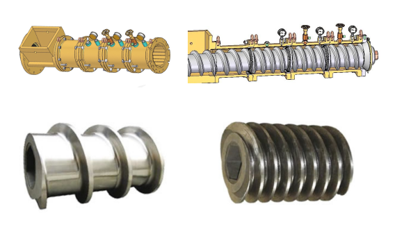
In general, when the gap between the screw flight and barrel liner inner diameter is 2.5 times larger than the new or unworn state, wear causes unstable production processes. Wear is caused by friction between material and screw/barrel inner wall, which is inevitable as mechanical energy converts to thermal energy. Effective measures to reduce wear include:Reducing raw material particle size distribution: Smaller particles gelatinize more easily and have lower abrasiveness.Increasing processing moisture: Reduces material viscosity and screw-material friction, thus lowering mechanical energy input and wear. Adding fat or oil also reduces friction by acting as a lubricant.Another type of wear is corrosive wear, usually caused by a low pH (acidic) environment from added salts in the formulation.


Share:
Related News
The Mufeng Ghana Feed Production Line Project Is Progressing Rapidly Helping To Upgrade The Local Livestock And Aquaculture Industries
2025-11-27
On November 27th, Henan Mufeng Intelligent Equipment Co., Ltd., a leading domestic manufacturer of professional animal feed production line equipment, reported good news from its overseas projects. The company's 350-type pellet feed production line (capacity 3-5 tons/hour) and 500kg aquatic extruded feed production line projects in Ghana are progressing rapidly, with on-site feedback indicating that construction and commissioning are proceeding smoothly. The project owner highly praised the equipment's compatibility with the process and its efficiency.
Ten Reasons for Decline in Feed Hammer Mill Production Capacity and Corresponding Solutions
2026-04-08
Analysis of Causes for Reduced Hammer Mill Capacity and Corresponding Solutions The main approach for us to analyze the causes of reduced hammer mill capacity is: 1)Inspect the materials to be crushed; 2)Check the screen apertures; 3)Inspect the installation of the screen mesh; 4)Check the position of the feed guide plate; 5)Check the pulse jetting of the dust collector’s solenoid valve and inspect the filter bags; 6)Check the configuration of the dust collector’s fan; 7)Check the hammer-screen gap and wear status; 8)Check the wear status of the screen pressure plate; 9)Check the hole arrangement and opening rate of the screen mesh; 10)Check the air supply damper of the supporting impeller feeder; 11)Check if there is air leakage in the settling chamber (especially in the pneumatic conveying system); 12)For the secondary crushing process, inspect the formula materials and oil content.
Nordic Customers Are Welcome To Visit The Company
2021-10-07
Professional feed production line turnkey project supplier
Provide a complete set of factory solutions for animal feed, aquatic expanded feed, pet food, cat litter pellets, biomass pellets, etc.!
Get A Free Quote

    *

    *

    Production Line

    Production Capacity

    *Messages

    x